
Insize
JEU DE BASE MAGNÉTIQUE ET CADRAN INDICATEUR INSIZE 5002-4E
Regular price CA$101.83Unit price /UnavailableVery low stock (2 units) Sale
SaleACCUSIZE
Sale price CA$20.83 Regular price CA$22.73Unit price /UnavailableLow stock (6 units) Sold out
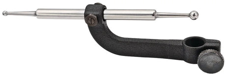
Starrett
STARTRETT 670B 52724 INDICATOR MOUNT
Regular price CA$125.07Unit price /UnavailableVery low stock (2 units)
Insize
1" .001 INSIZE DIAL INDICATOR (2307-105)
Regular price CA$49.64Unit price /UnavailableLow stock (9 units)
Mitutoyo
MITUTOYO DIGITAL INDICATOR 543-783-10
Regular price CA$285.71Unit price /UnavailableVery low stock (1 unit)Équipement Polar
MAGNETIC Z AXIS ZERO INDICATOR
Sale price CA$186.67 Regular price CA$203.64Unit price /Unavailable


Our recommendations
-

Klein tools
KLEIN ET450 CIRCUIT DETECTOR ASSEMBLY
Regular price CA$399.99Unit price /UnavailableVery low stock (1 unit) -
Sale
ACCUSIZE
Sale price CA$20.83 Regular price CA$22.73Unit price /UnavailableLow stock (6 units) -

Jet
3/8" DR METRIC CHROME SOCKET WRENCH SET 30PCS JET 600234
Regular price CA$164.10Unit price /UnavailableVery low stock (2 units) -

ATD
SNAP RING 300 PIECES SNAP RING ATD 354
Regular price CA$41.19Unit price /UnavailableIn stock (43 units) -
Sale
Dewalt
Sale price CA$159.00 Regular price CA$198.00Unit price /UnavailableLow stock (9 units) -
-
Stanley
Regular price CA$19.44Unit price /UnavailableLow stock (8 units) -
-
-
-
Dewalt
DEWALT DWFP71917 16 GA AIR FINISH NAILER
Regular price CA$269.00Unit price /UnavailableVery low stock (2 units) -
-
 Sold out
 -

Klein tools
Regular price CA$64.98Unit price /UnavailableVery low stock (1 unit) -
Dewalt
IMPACT 1/2'' 1200 FT-LBS DEWALT (TOOL)
Regular price CA$448.00Unit price /UnavailableIn stock (11 units) -
-

Dewalt
IMPACT 1/2'' 20V. NEW GEN (TOOL ONLY)
Regular price CA$389.00Unit price /UnavailableVery low stock (1 unit) -
Dewalt
IMPACT 1/2'' COMPACT ATOMIC (TOOL)
Regular price CA$218.00Unit price /UnavailableVery low stock (1 unit) -
-

Dewalt
IMPACT 1/2'' COMPACT ATOMIC (TOOL)
Regular price CA$309.00Unit price /UnavailableLow stock (7 units) -
Dewalt
1/2" LIGHTWEIGHT IMPACT WRENCH (TOOL ONLY) DCF892B
Regular price CA$349.00Unit price /UnavailableLow stock (4 units) -


Complete Guide to Choosing Your Precision Measurement Indicators
What is the difference between a dial indicator and a lever indicator?
Their rack and pinion mechanism converts the linear movement of the probe into the rotation of the hands on a graduated dial.
Lever indicators, also called test indicators, measure displacement perpendicular or parallel to their axis.
Dial indicators are ideal for measuring runout of rotating parts on a lathe, and checking the flatness of milling machine tables.
Lever indicators excel at measurements in confined spaces, checking the alignment of lathe centers, and inspecting perpendicular surfaces.
Prefer a lever indicator for delicate tasks requiring difficult access or multi-directional measurements on complex machine tools.
How to choose the appropriate resolution for your precision needs?
Standard indicators offer a resolution of 0.01 mm or 0.001 in, which is sufficient for most general machine shop applications.
High-precision indicators achieve 0.001 mm or 0.0001 in for controlling tight tolerances on critical parts.
For general machining of parts with tolerances of ±0.05 mm, a 0.01 mm resolution indicator is perfectly adequate. Applications requiring tolerances of ±0.02 mm or less.
The fundamental principle states that the instrument's resolution must be at least 10 times finer than the tolerance to be controlled for reliable measurements.
Also consider the indicator's total permissible error, generally specified by the manufacturer.
Professional indicators guarantee an accuracy of ±0.002 mm over the entire range for 0.01 mm resolution, and ±0.0005 mm for 0.001 mm resolution.
Polar Industrial Equipment advises you on selecting the optimal resolution according to your quality control requirements and metrology budgets.
Metric versus Imperial Indicators: Understanding Measurement Systems
Metric indicators display graduations in millimeters with typical resolutions of 0.01 mm (one hundredth) for standard models and 0.001 mm (one thousandth) for high precision. Imperial indicators graduate in inches with resolutions of 0.001 in (one thousandth of an inch) for standard and 0.0001 in (one ten-thousandth) for critical applications.
Care and Handling: Extending the Life of Your Indicators
Runout inspection is the most frequent use: install the indicator on a magnetic stand, position the probe against the rotating part, and rotate the part to detect eccentricity.
A maximum variation of 0.02 mm indicates acceptable concentricity for most mechanical applications.
Aligning parts on a milling machine requires a lever-type indicator for precise scanning of reference surfaces.
Position the probe perpendicular to the surface, move the table in X or Y, and adjust until a constant reading is obtained along the entire length.
This technique ensures perfect parallelism between the part and machine axes for precise machining of grooves and pockets.
Checking the flatness of tables and plates uses a dial indicator mounted on a magnetic stand.
Move the indicator systematically across the entire surface according to a grid of measurement points. Note the variations to map irregularities.
New machine tool tables show flatness of less than 0.01 mm over 300 mm.
Maintenance technicians use these measurements to schedule grinding or adjustment of guideways.
Professional Applications: Optimizing Workshop Indicators
Runout inspection is the most frequent use: install the indicator on a magnetic stand, position the probe against the rotating part.
A maximum variation of 0.02 mm indicates acceptable concentricity for most mechanical applications.
Aligning parts on a milling machine requires a lever indicator for precise scanning of reference surfaces.
Position the probe perpendicular to the surface, move the table in X or Y, and adjust until a constant reading is obtained over the entire length.
This technique ensures perfect parallelism between the part and machine axes for precise machining of grooves and pockets.
Checking the flatness of tables and plates uses a dial indicator mounted on a magnetic stand.
Systematically move the indicator over the entire surface according to a grid of measurement points. Note the variations to map irregularities.
New machine tool tables exhibit flatness of less than 0.01 mm over 300 mm. Maintenance technicians use these measurements to program grinding or adjustment of guides.